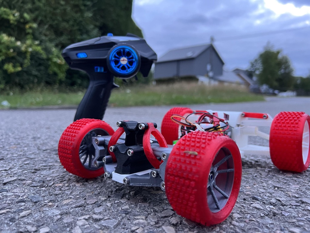
3D Printed RC Car
A hands-on project focused on designing, printing, and assembling a functional RC car using 3D printed components and basic electronics.
What you'll learn
Overview
This project challenges you to design and build a fully functional 3D printed RC car by combining mechanical design, CAD modeling, and electronics integration.
You will:
- Design and assemble multiple custom parts
- Replace off-the-shelf components with 3D printed alternatives
- Explore how mechanical and electrical systems work together
This is a great project to strengthen your CAD skills, prototyping ability, and system thinking.
Project Video
Materials
📦 Materials
⚡ Electronics
Build Steps
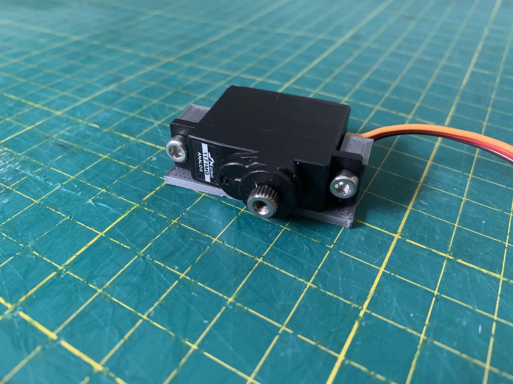
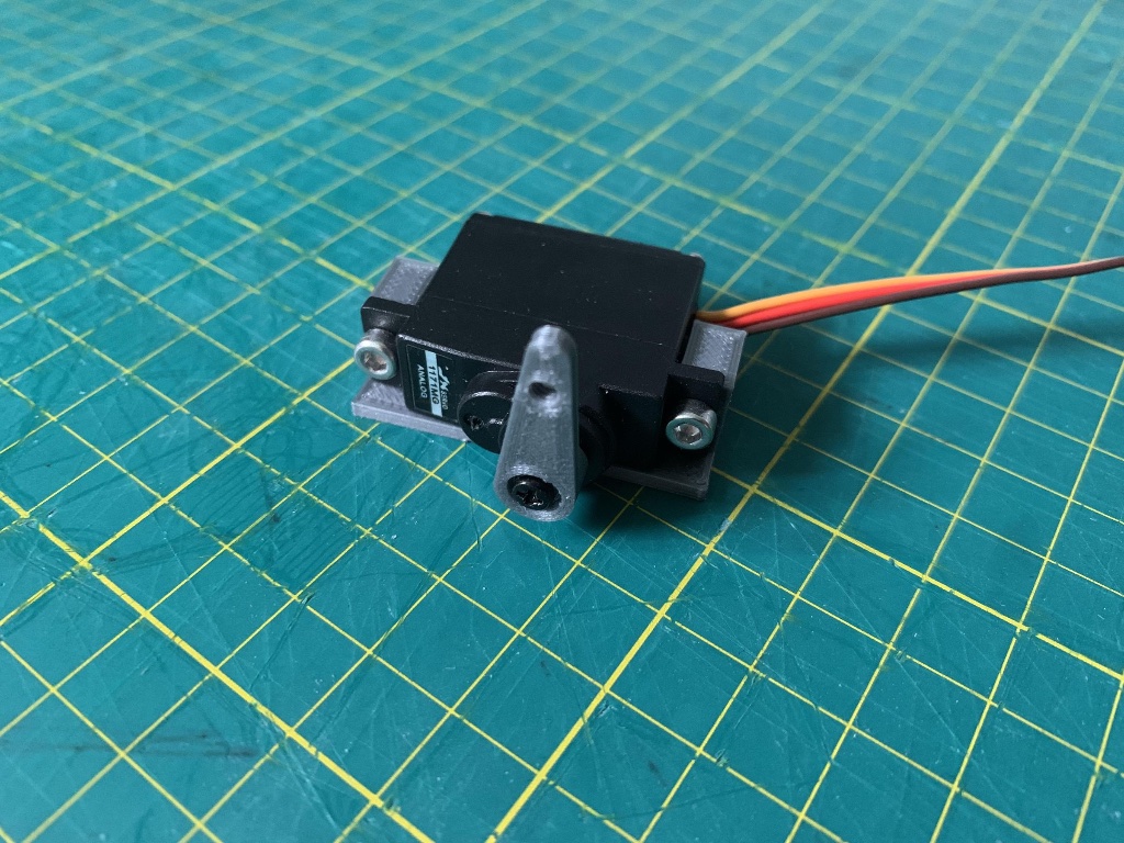
Attach the servo to the mount using two 10mm screws. Adjust the bracket if your servo size differs from the PS-1171MG. Attach the servo arm securely using the original screw that came with the servo. Files needed: • servo mount.stl • servo arm.stl
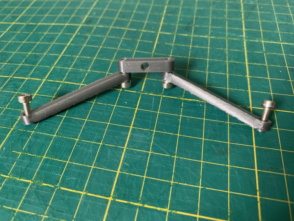
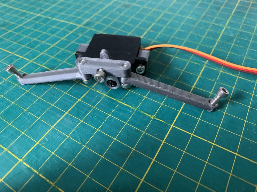
Ensure all arms rotate freely before assembly. File any edges if needed to remove print artifacts. Attach both steering arms to the center arm loosely — do not overtighten yet. Connect the center arm to the servo arm using a 10mm screw. Files needed: • Steering arm.stl • center arm.stl
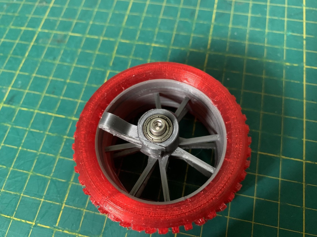
Insert bearings into the wheel hub parts — press them in firmly until flush. Pass a 30mm screw through the center of the hub, add a washer, then secure. Use a nylon locking nut to prevent the wheel from loosening during use. Files needed: • Wheel Bracket.stl • Hub.stl • Tyre.stl
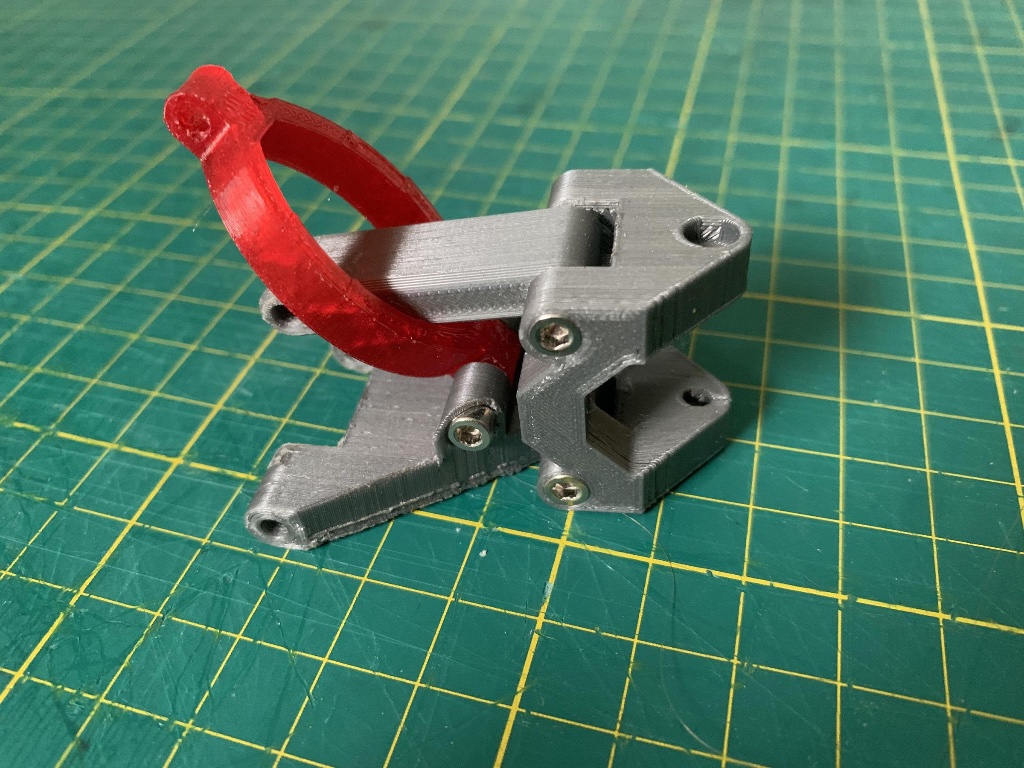
Check all parts fit smoothly and allow free movement before assembling. Attach: • Wishbones to the steering bracket using 22mm screws • Suspension piece in the correct orientation Files needed: • Front arm.stl • Front arm top.stl • Steering Bracket.stl • Suspension.stl
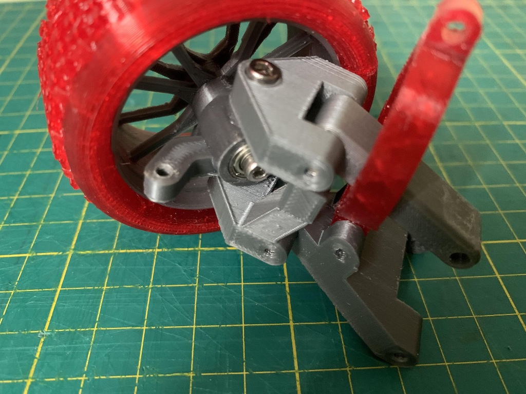
Secure the front wheel to the steering bracket using 8mm screws. Ensure the wheel spins freely with no rubbing against the bracket or suspension arms.
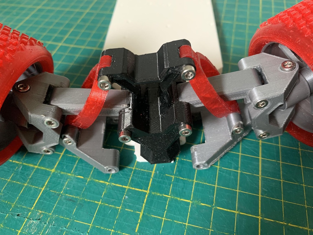
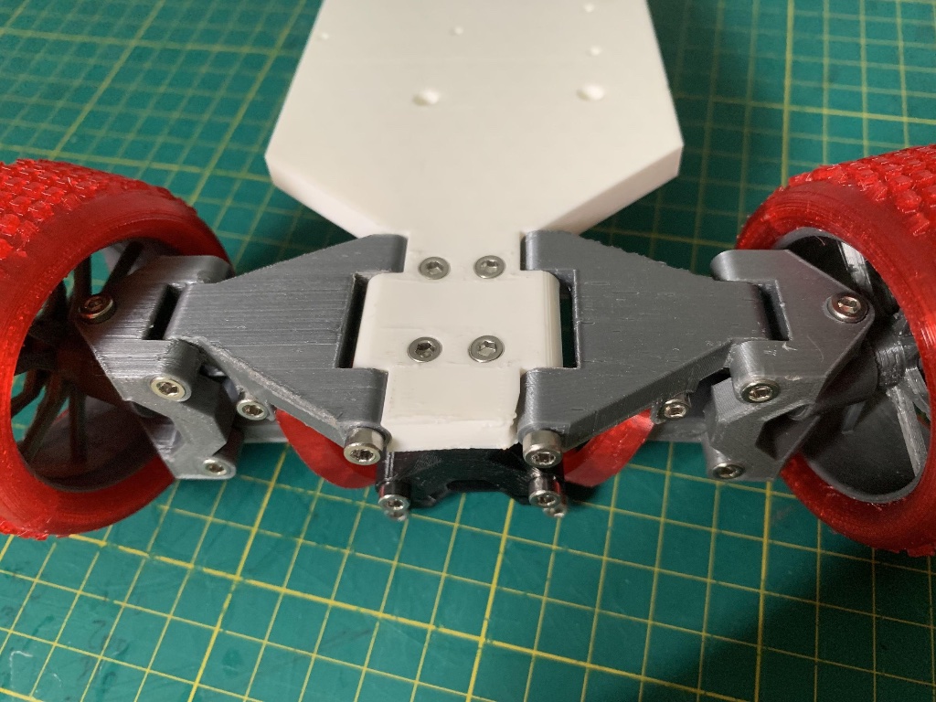
Ensure smooth movement across all joints before finalising. Attach: • Suspension using 16mm screws • Top wishbones using 30mm screws • Base connections using 22mm and 40mm screws File needed: • Front arm Bracket.stl
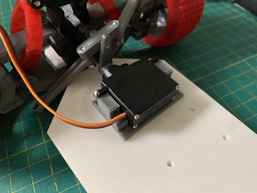
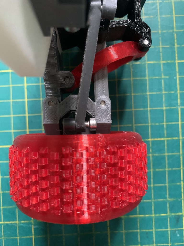

Mount the servo onto the chassis base using 10mm screws. Connect the steering arms to the wheel connector, allowing a small amount of vertical movement for suspension travel. Check that turning the servo arm left and right steers both front wheels simultaneously and symmetrically.
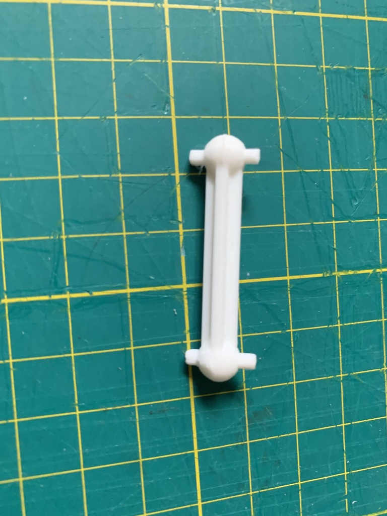
Insert the steel pins into both halves of the drive shaft connector. Ensure a tight, secure fit — the pins should not be loose. If they are, add a small drop of CA glue. Files needed: • Driver arm.stl • Pin.stl
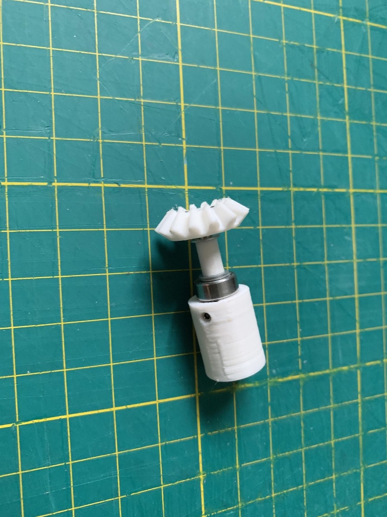
Cut a 3mm steel rod to exactly 23mm in length. Slide the small bevel gear onto the rod and secure it firmly using the M2.5 grub screw. Files needed: • Inner Driver Gear.stl • Back gearbox connector.stl • Long washer.stl
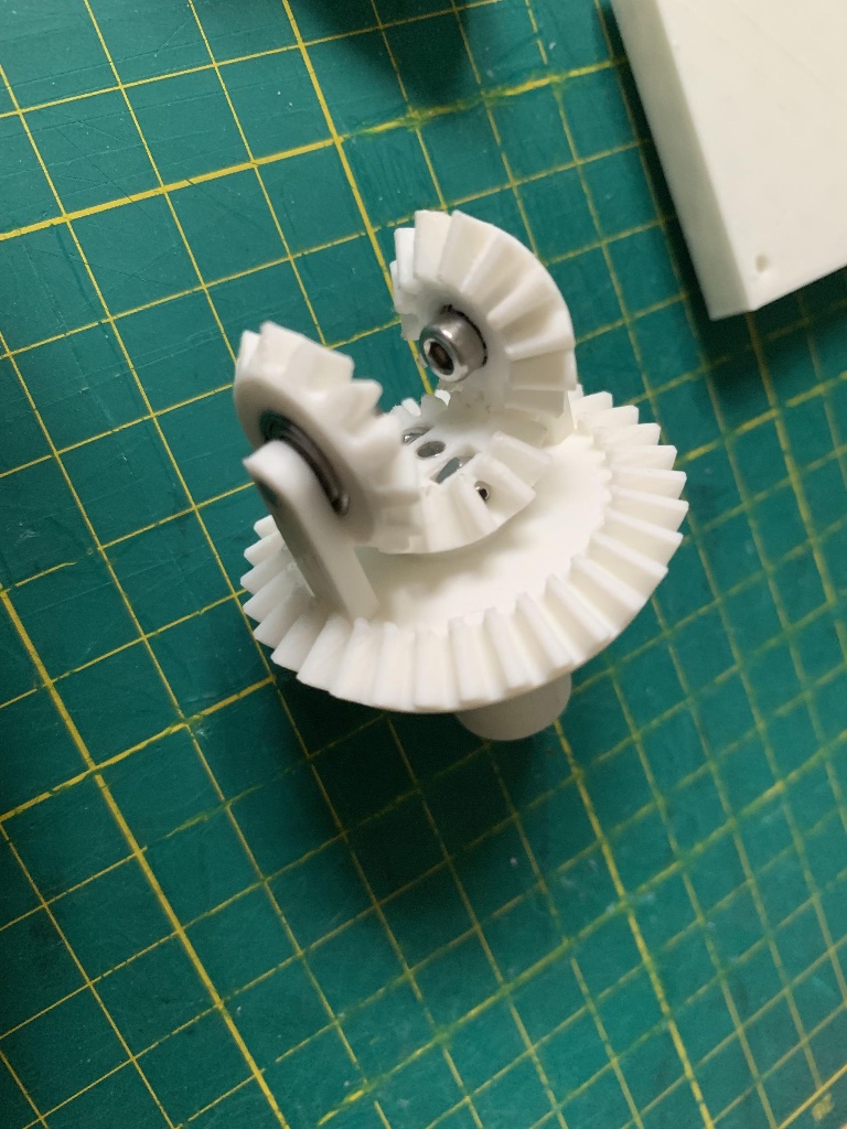
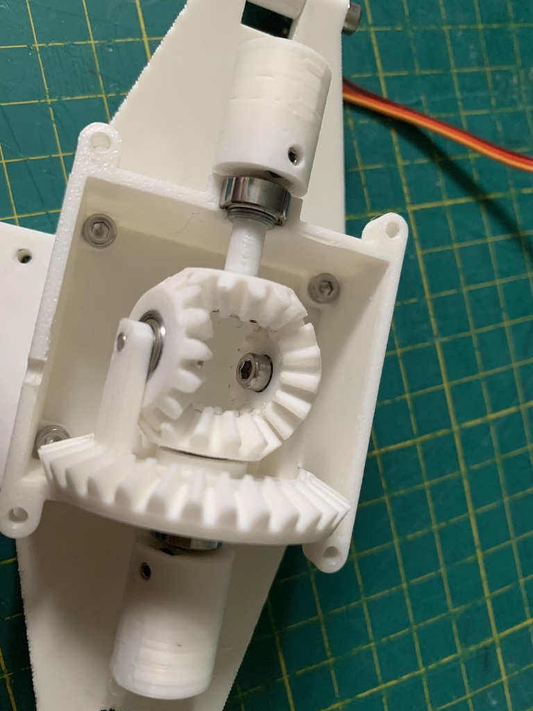
Press a bearing into the center of the large bevel gear until fully seated. Attach the gear arm to the assembly using 8mm screws. Carefully align both bevel gears so they mesh smoothly. Files needed: • Back gearbox connector.stl • Gear Arm.stl • Large gear.stl • Small Gear.stl
Reflection Questions
Powered by SilidLMS