Designing for 3D Printing
Core design principles for FFF 3D printing
In this short online course, you'll learn the core design principles for FFF (Fused Filament Fabrication) 3D printing. Through real CAD examples, you'll see how and why designs succeed or fail when printed. This course focuses on design rather than slicer settings, with all examples using standard settings to highlight the impact of design decisions. Each section focuses on a key principle, helping you understand how to design parts that print reliably and perform as intended.
This course can be followed in different ways:
You can simply watch the videos to understand the core design principles for 3D printing. Each section uses real CAD examples to show how and why designs succeed or fail.
For a more hands-on experience, you can also 3D print the demo model set and explore the principles physically as you progress through the course.
Once you've completed the course, the Design Principles Guide can be used as a quick reference when designing your own models.
Design Principles Model Set
A set of test models demonstrating key 3D printing principles such as overhangs, bridging and tolerance. Print and refer to them as you work through the course to see how each principle behaves in real life. Includes 30 mm (recommended) and 60 mm versions. The 60 mm models match the videos but do not include the base.
Download Model Set (ZIP)Demo Model Set
21 STLs in this file1. Overhangs
An overhang is any part of a 3D model that extends outward, with little or no material beneath it to support it during printing.
Key Learnings
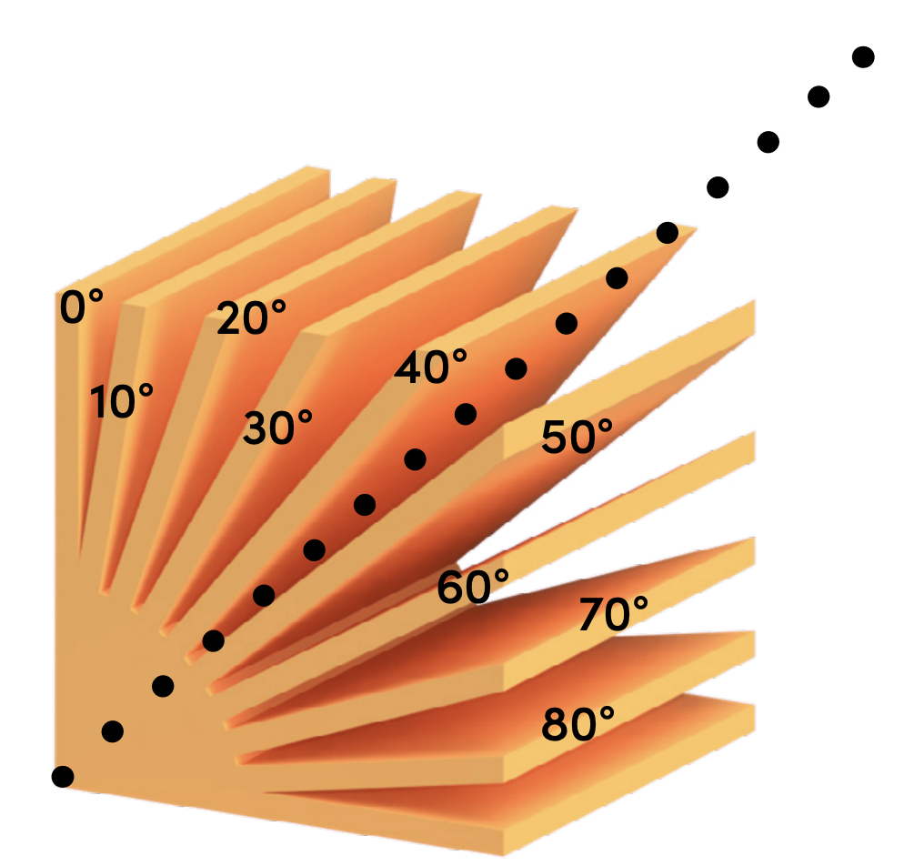
The steeper the overhang angle, the worse the surface quality
As the angle increases, each new layer has less material beneath it for support, often leading to sagging and rough undersides. As a general rule, aim to keep overhangs at 45° or less where possible.
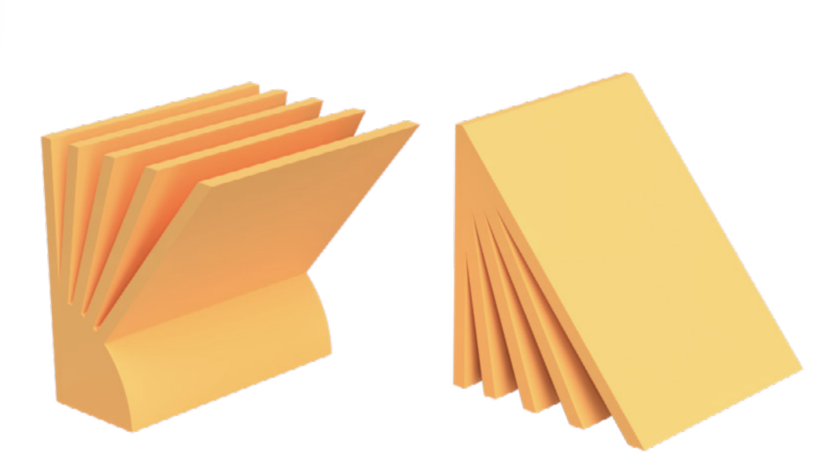
Splitting and reorienting parts is a common workaround
By changing the orientation or breaking a model into multiple parts, overhangs can be reduced or eliminated. This allows each part to print cleanly without relying on support material.
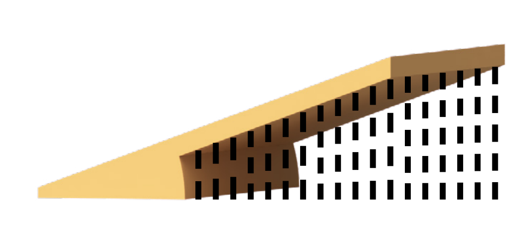
Support material can be used, but it has trade-offs
Supports can hold up overhangs during printing and are broken off after printing, but increase print time and material use. They can also leave marks or rough surfaces when removed, reducing the final finish quality.
2. Bridging
A bridge is a horizontal span between two supported points, with no material beneath it during printing.
Key Learnings
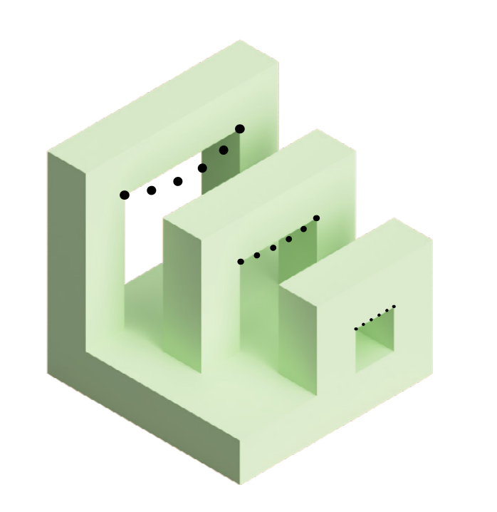
The longer the bridge span, the more the filament will sag
As the distance between supports increases, sagging becomes more pronounced, leading to rough undersides. Aim to keep bridges under 12mm where possible, unless surface quality or fit is not critical.
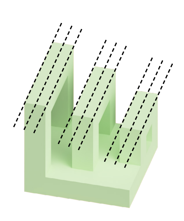
Bridging mainly affects the underside of a print
The top surface is usually supported by subsequent layers and often appears clean and well formed. Any roughness caused by bridging is typically limited to the underside of the span.
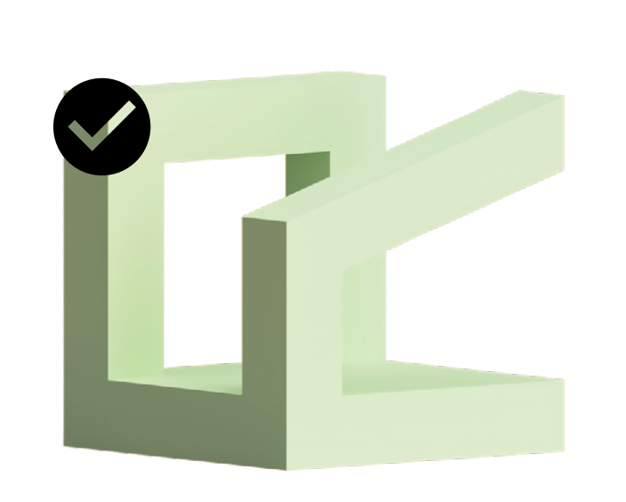
Bridges are often better than steep overhangs
A horizontal bridge can span a gap more cleanly than a steep overhang can print without support. Where possible, use bridging instead of steep angles to improve print quality.
3. Minimum Features
Minimum features refer to the smallest details a 3D printer can reliably produce, such as thin walls or fine surface details.
Key Learnings
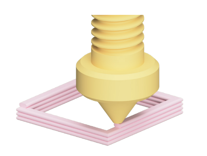
Minimum feature size is determined by nozzle diameter
The printer lays down plastic in lines, typically around 0.4mm wide on most desktop machines. Features smaller than this are at the absolute limit and may not print reliably.
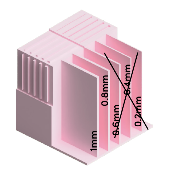
Aim for features of at least 0.8 mm or larger
Designing at around twice the nozzle diameter allows multiple lines of material, improving strength and consistency. Features closer to the minimum are more fragile and less predictable.
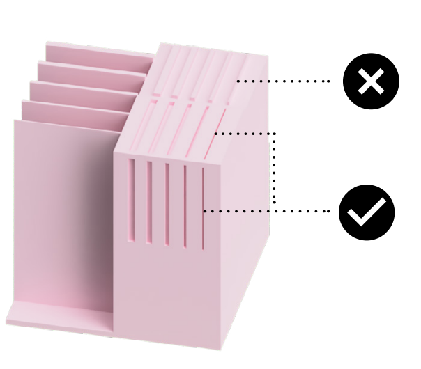
Engraved details can be smaller than raised features
Engraving creates gaps between printed lines rather than adding thin lines of material, allowing finer details to appear. However, designing too close to the limit can still reduce reliability.
4. Orientation
Orientation refers to how a 3D model is positioned on the build plate during printing.
Key Learnings
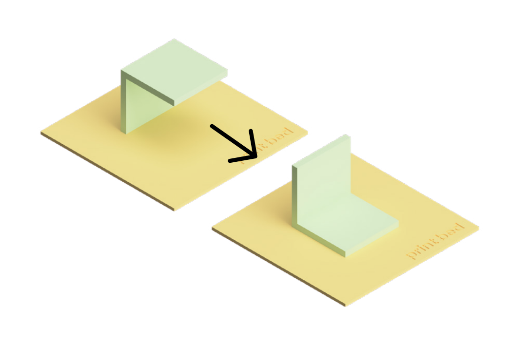
Orientation can be used to increase contact with the build plate
Placing a larger, flatter face on the build plate improves adhesion and reduces the risk of the print detaching. Small or narrow contact areas are less stable and more likely to fail.
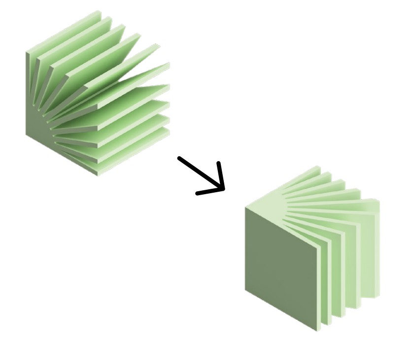
Changing orientation can reduce overhangs and supports
By considering overhangs during the design process, you can rotate parts to turn unsupported features into supported ones. This allows models to print cleanly without support material, improving surface quality and efficiency.
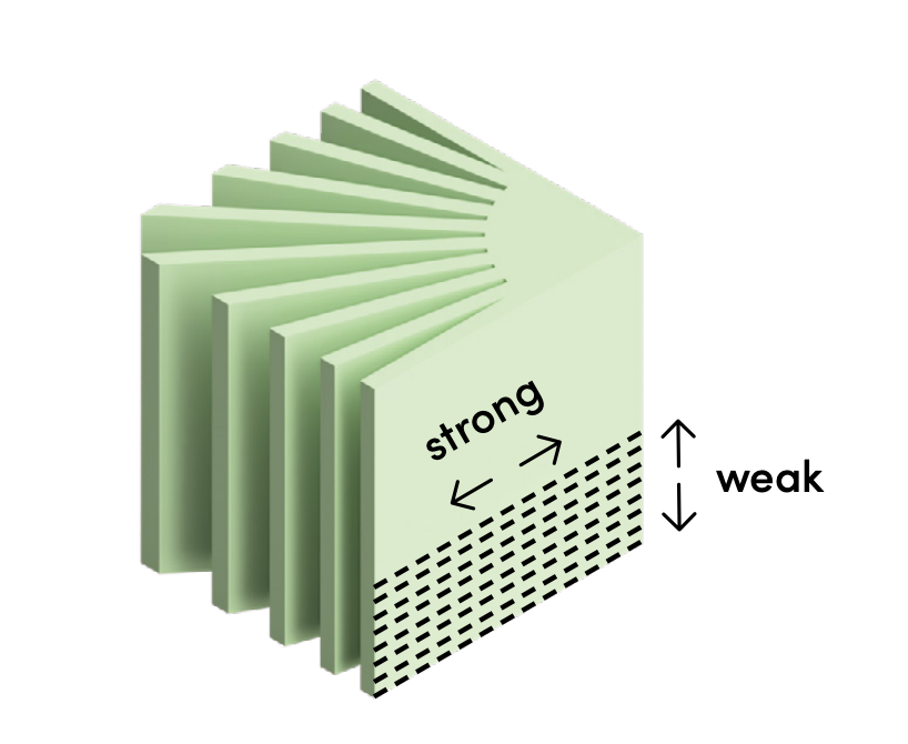
Parts are stronger along the direction of the layers
Because parts are built layer by layer, they are strongest along the layers and weaker between them. This is similar to wood grain, which is harder to break along the grain than across it.
5. Fillets
A fillet is the rounding of an interior or exterior corner where two features meet. It creates a smooth, curved transition between surfaces.
Key Learnings
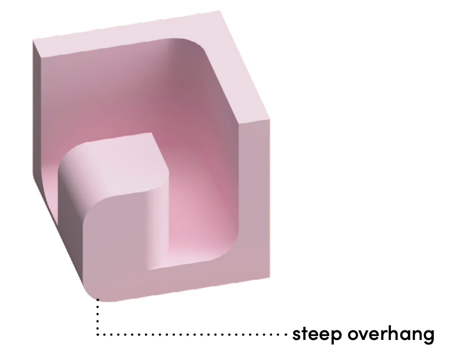
Fillets on undersides behave like overhangs
When placed on downward-facing edges, fillets have no support beneath them and can sag during printing. Keep these fillets small to reduce overhang angles and improve surface quality.
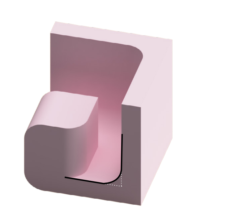
Internal fillets improve strength and print reliably
Adding a radius to internal corners spreads stress more evenly and reduces weak points. These fillets are usually well supported during printing and produce consistent results.
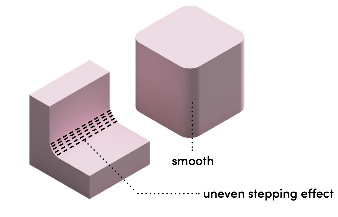
Fillet quality depends on their orientation
Vertical fillets print as smooth curves, while horizontal fillets are built in layers and may show visible stepping. Choosing the right orientation can improve both appearance and performance.
6. Chamfers
A chamfer is an angled face added where two surfaces meet. It replaces a sharp edge with a flat, angled transition.
Key Learnings
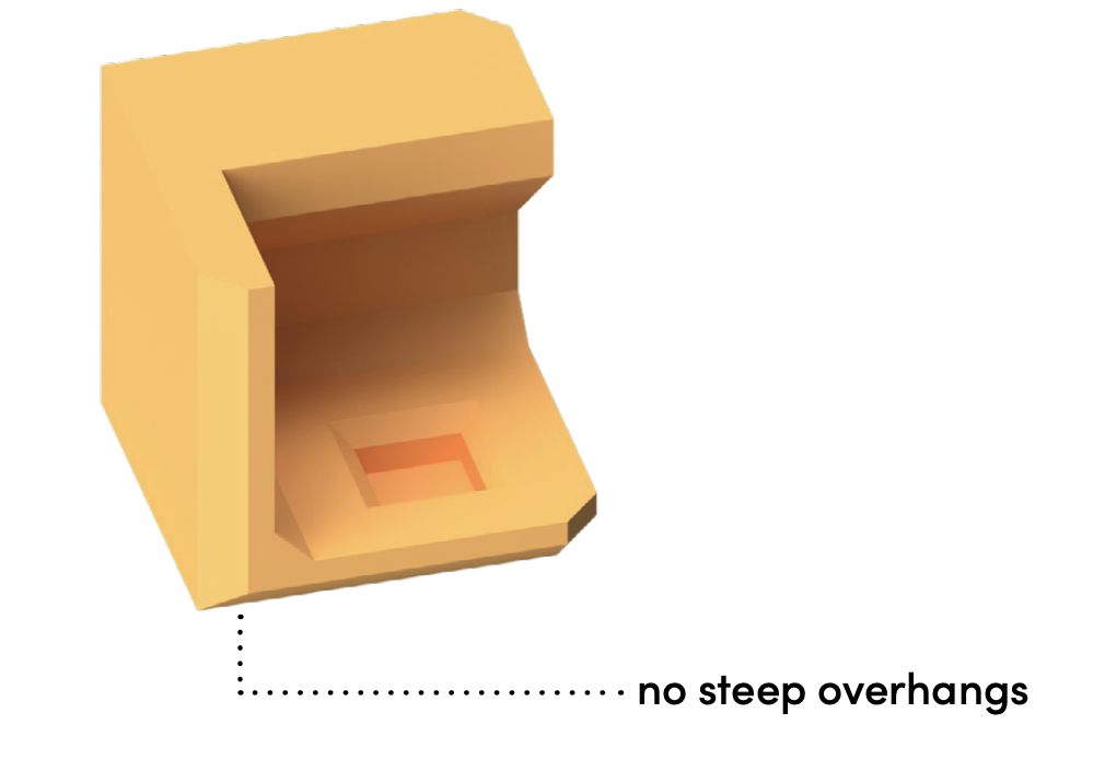
Chamfers can improve strength and print reliably
They reduce sharp corners and help spread stress through a part, improving durability, although not to the same extent as fillets. They are also more predictable to print, especially on underside edges, as they are typically around 45°.
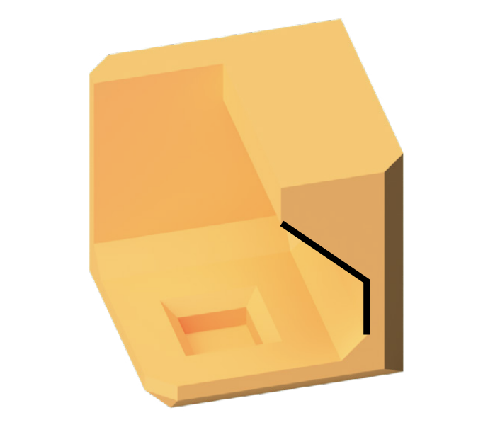
Chamfers can replace unsupported horizontal surfaces
A flat edge would create an unsupported overhang, but a chamfer turns it into a gradual slope. This allows surfaces to print cleanly without supports, even on underside features.
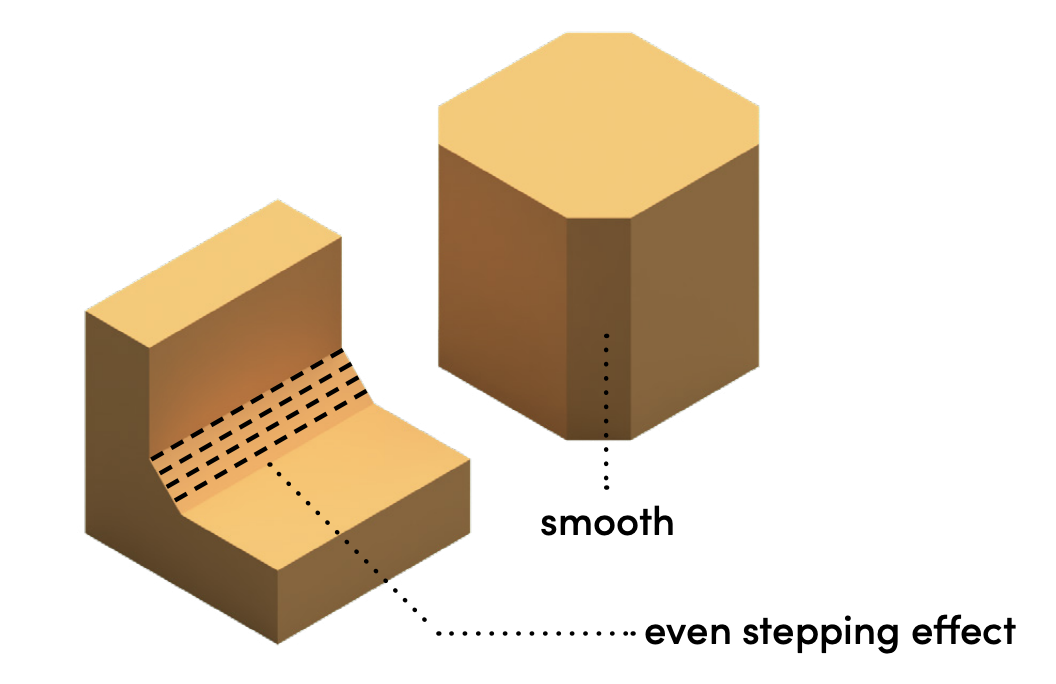
Chamfers produce controlled, consistent surfaces
Because they are built at a constant angle, any stair stepping appears even and predictable. This often looks more consistent than curved features, where stair stepping can be more noticeable.
7. Tolerance
Tolerance describes the acceptable deviation from an intended size in a printed part. In 3D printing, parts are rarely exact, so designs need to account for these small differences.
Key Learnings
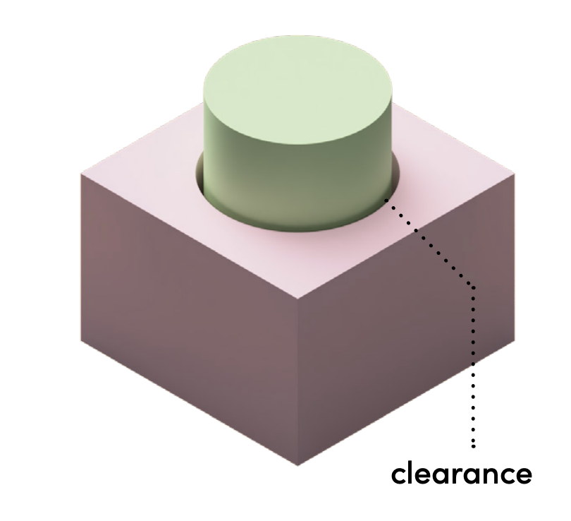
Clearance allows parts to fit and function reliably
Clearance is a small intentional gap designed into parts in CAD to account for variations in 3D printing. Without it, parts may not fit together or move as intended.
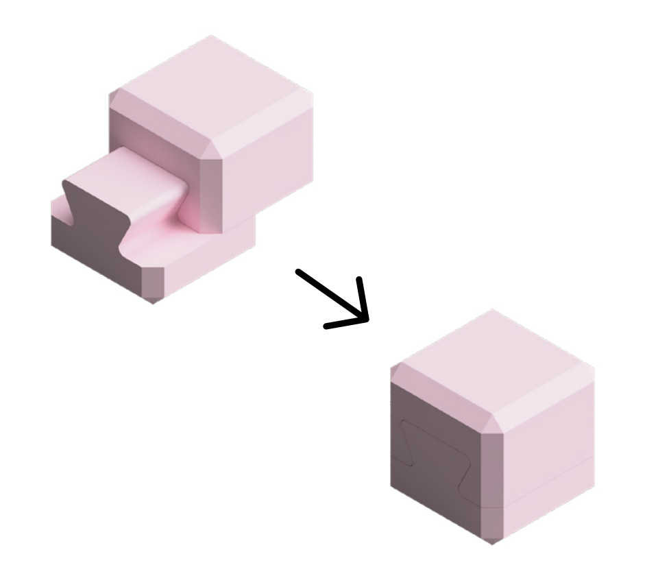
Small clearances can be used for tighter fitting parts
Clearances around 0.1 to 0.2mm are commonly used for parts that need to fit together securely, such as press fits or dovetail joints. These values provide a balance between accuracy and reliable assembly.
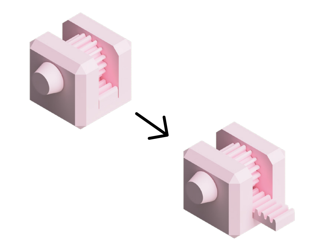
Larger clearances can be used for moving parts
Clearances around 0.3 to 0.4mm are better suited to mechanisms with rotation or sliding motion. The extra space helps reduce friction and allows parts to move freely and reliably.
8. Holes
A hole is an opening created by removing material from a solid body. In 3D printing, hole quality depends on size, orientation, and shape.
Key Learnings
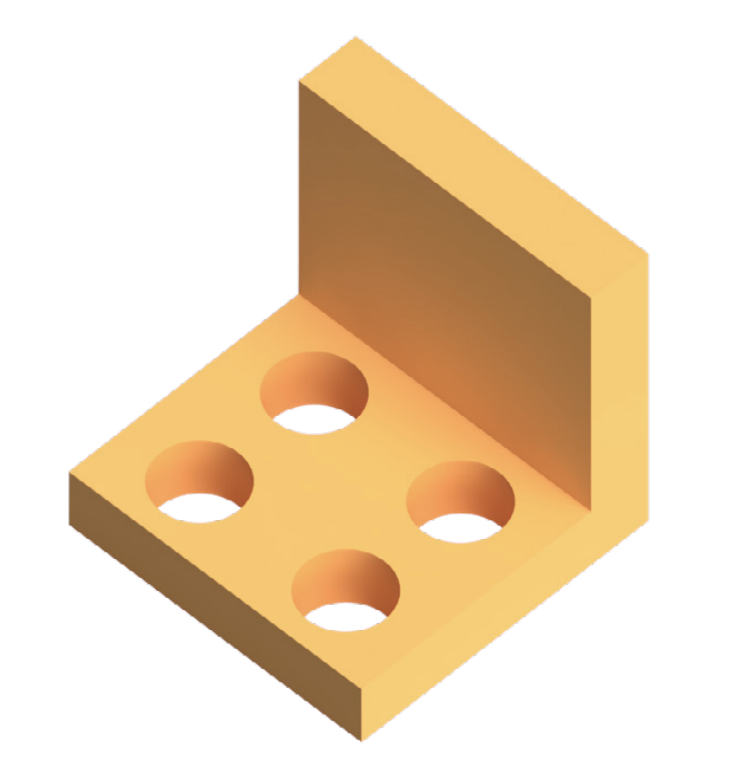
Vertical holes print very accurately
When printed upright, each layer is supported by the one below, allowing the intended geometry to be reproduced cleanly and consistently.
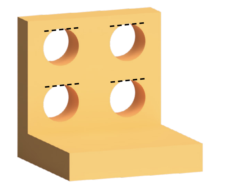
Horizontal holes may create overhangs
When printed on their side, the top of the hole becomes an unsupported span, which can lead to sagging or a flattened surface.
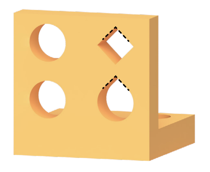
Horizontal holes can be improved by changing shape
Using shapes such as teardrops or diamonds replaces flat overhangs with angled surfaces, allowing layers to build gradually and print cleanly without support.
9. Sharp + Narrow Points
Sharp points occur when geometry tapers down to an extremely small area or a perfect tip.
Key Learnings
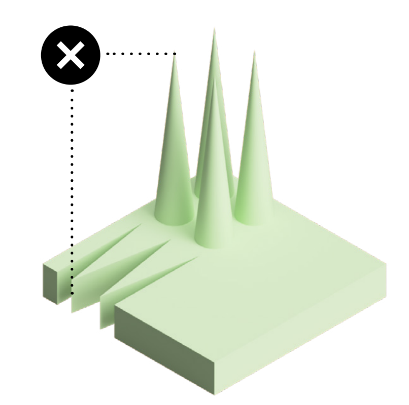
Perfectly sharp tips cannot be printed
As geometry narrows below the printer's minimum feature size, the slicer cannot generate toolpaths. This causes tips to be shortened or rounded instead of forming a true point.
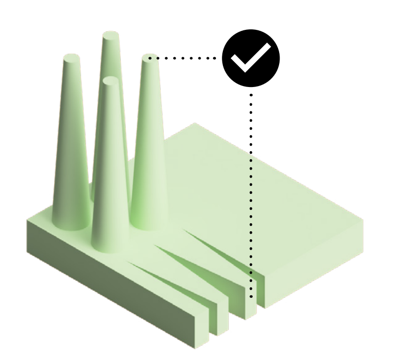
Adding a small flat tip improves reliability
A defined flat surface ensures the feature remains within printable limits, allowing it to reach the intended size. This produces more consistent and predictable results.
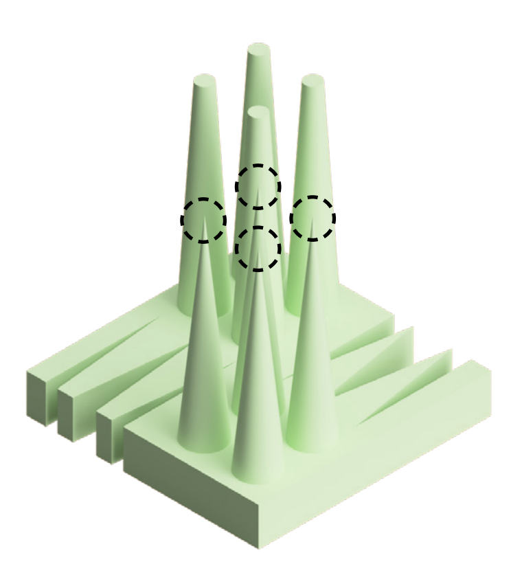
Vertical spikes snap very easily
Because they are built layer by layer, vertical spikes are weak between layers and can break easily. Adjusting orientation or adding a flat tip helps improve strength and durability.
Bonus Section: Multicolour
Multicolour 3D printing allows a single part to be produced using multiple filaments. This is commonly achieved using filament switching systems such as an AMS.
Key Learnings
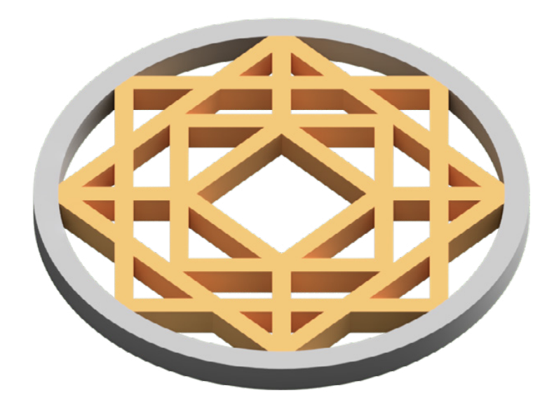
Multicolour prints can significantly increase print time
Each colour change requires the printer to switch filament and purge material, which adds time and waste. Designs with frequent colour changes across many layers are the least efficient.
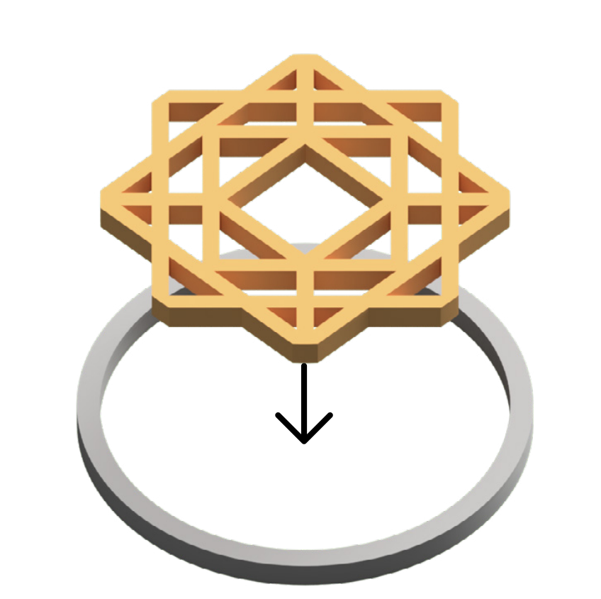
Separate parts can reduce time and waste
Printing parts in different colours as separate components avoids filament switching and produces faster, more efficient prints. A small clearance, around 0.1mm, can be used to create a simple press fit for assembly.
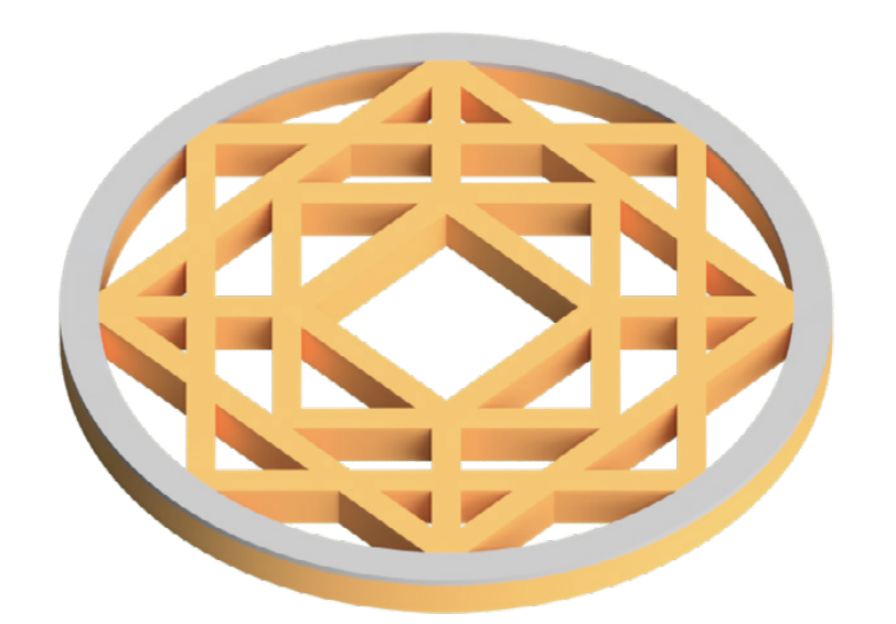
Limiting colour changes improves efficiency
Restricting colour changes to specific areas, such as the top layers, reduces the number of filament swaps. This helps balance print time, material use, and overall appearance.